Arduino with XBee and ROS
25 Oct 2014Not so long ago, I was trying to figure out how to communicate with my Arduino Bot using XBee Series 2 radios (API mode) and Robot Operating System (ROS). It took me a while to make the XBee module work in API mode and I’m still learning the ins and outs of the ROS. So this is probably not the most optimal solution, but I bet it is a good starting point.
Here is a picture of my bot:
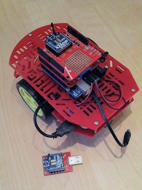
This guy is controlled by simply connecting an XBee explorer dongle to Ubuntu, running ROS, and then just using the keyboard to make it move.
Requirements
These are just to show you what I used for my project. It could be much simpler, like turning a LED on or off remotely.
Hardware
- 1x Magician Chassis
- 1x Arduino Uno “brain” for the bot.
- 1x Motor Driver Shield to control two DC motors.
- 2x XBee Series 2 used for wireless communication.
- 1x XBee Explorer Dongle to connect XBee radio to your computer.
- 1x XBee Shield for connecting XBee to arduino board.
- 1x PowerGen® 5200mAh battery pack to power arduino bot.
- 1x Computer (PC, Mac) to run ROS.
- (Optional) Jumper wires very helpful in projects like this.
- You might need these accessories:
Software
Install Ubuntu (download)
I used a Ubuntu 14.04 64bit virtual machine, running in VirtualBox. Ubuntu currently is the only Linux distribution officially supported by ROS.
Install ROS
I recommend going to www.ros.org. It has really good installation instructions. Also, make sure to go through beginner tutorials to better understand how ROS works.
X-CTU Software (download)
You will need this to configure XBee radios.
Arduino IDE (download)
If you want to be able to program Arduino, this is must-have (yes, you can do it the HARD way, but I won’t recommend it).
Assembly Notes
You can find Magician Chasis assembly instructions here. If you don’t have this assembly, you can just look at these instructions to get the idea of how it comes together.
Also, under the References section, I’ve posted a couple of links that should help you with XBee and Ardumoto shields.
Make sure that you connect your XBee router module to the Arduino. Use an XBee coordinator with the dongle to communicate with ROS (I will explain how to configure coordinator and router modules below).
Configuring XBee
First of all, write down the 64-bit serial number that is located on the bottom side of each module (it is unique and permanently assigned). We will use it for addressing (eg. 0013A200-XXXXXXXX). The first 4 bytes of this number are called DH (Destination Address High) and the last 4 bytes - DL (Destination Address Low) in XCTU application.
Prepare coordinator radio
ZigBee networks always have a single-coordinator radio. It is responsible for forming the network, handing out addresses and managing other functions to keep the network alive and healthy.
-
Pick one of the XBee modules (you can optionally mark it with a marker) and connect it to your computer using an XBee explorer dongle.
-
Launch X-CTU utility.
-
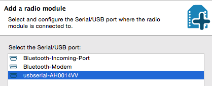
Click the “Add a radio module” button on the top left and select your radio (in my case, it was usbserial-AH0014VV) and click “Finish.”
You should see your XBee module listed on the left and its information loaded on the right (if information is not visible, just left click on your module):
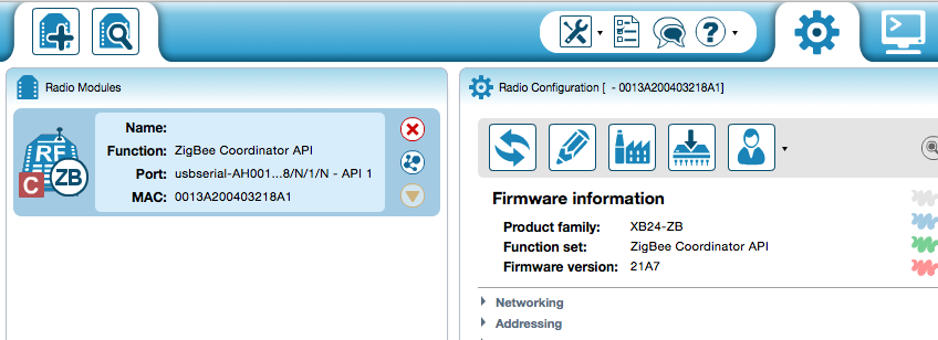
If you look at the picture above, you can see that the current “Function set” is ZigBee Coordinator API. If you see Router AT or similar, click on the “Update firmware” button, select ZigBee Coordinator API in the list and click “Finish.”
-
(Optional) I’d recommend clicking the “Load default firmware settings” button before performing the configuration.
-
For this radio, we need to configure three fields:
ID (PAN ID) - Used to uniquely identify your ZigBee network. Set it to a random hex number (eg. 1ABC)
DH (Destination Address High) - The first 4 bytes of the XBee address (serial number, for example: 0013A200)
DL (Destination Address Low) - The second part of this address
These are destination addresses, which means that you need to use a serial number for the XBee Router module, not the one we are configuring at the moment.
When you set these addresses, make sure to click the “Write radio settings” button.
At this point, your coordinator module is configured.
Prepare router radio
Connect the second XBee module (using XBee explorer dongle). Add it to the XCTU module list and this time, pick ZigBee Router API for the “Function set” (use the “Update firmware” button). For this radio, you need to set the same network PAN ID as you set before. Put in DH and DL addresses of the coordinator module. Don’t forget to click the “Write radio settings” button.
Also, before you disconnect your XBee module, go to the addressing section in XCTU and write down MY (16-bit Network Address) for the module. You will need it when setting up the ROS node.
Both XBee modules should now be ready. You can set them aside for now.
Programming Arduino
If you never launched Arduino IDE before, launch it now so that it creates an Arduino folder in your user’s Documents folder. Now, go to this new folder and clone the ArduinoBot repository:
$ cd ~/Documents/Arduino/
$ git clone https://github.com/dariusbakunas/ArduinoBot.git
You will also need the XBee library for your Arduino board:
$ cd ~/Documents/Arduino/libraries/
$ git clone https://code.google.com/p/xbee-arduino/
Now, launch Arduino IDE (relaunch if it was already open). Open the “File” menu. Go to the “Sketchbook” submenu and open the newly available RedWheeler sketch:

At the top of the sketch, you will notice these lines:
//ardumoto shield
int PWM_A = 3;
int PWM_B = 11;
int DIR_A = 12;
int DIR_B = 13;
These are standard pin settings for the Arduino DC motor shield. You should see the markings with the numbers on the shield itself (double check just in case). Now, click the “Verify” button in Arduino IDE and make sure the sketch compiles without any problems:

Now, connect your Arduino board using a USB port.
If you have an XBee shield already attached to the Arduino board, you need to make sure that the UART switch is set to the DLINE position (it is located on the XBee shield). Otherwise, you won’t be able to upload the sketch.
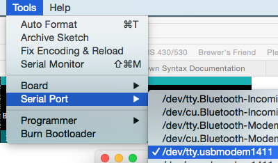
Go back to the Arduino IDE and select your Arduino board under the tools menu (in my case, it was tty.usbmodem1411, it could be different):
And then finally, click the “Upload” button. If all goes well, your Arduino is ready and you can disconnect it for now.
Installing ROS packages
At this point, you need to log in to your Ubuntu system that has ROS installed. If you haven’t done so already, create the ROS Workspace:
$ mkdir -p ~/catkin_ws/src
$ cd ~/catkin_ws/src
$ catkin_init_workspace
Build it:
$ cd ~/catkin_ws/
$ catkin_make
Activate it:
$ source ~/catkin_ws/devel/setup.bashI recommend putting the last line in your .bash_profile if you don’t want to manually switch to this workspace every time you login. First, you need to install the Python XBee library:
$ pip install xbee --userNow, it is time to download the ROS package that I’ve created for this project:
$ cd ~/catkin_ws/src
$ git clone https://github.com/dariusbakunas/arduino_bot_ros.git
One thing you should change before going any further is your XBee router module address:
$ cd ~/catkin_ws/src/arduino_bot_ros
$ nano src/scripts/cmd_vel_listener.py
Find definitions for XBEE_ADDR_LONG and XBEE_ADDR_SHORT. You need to set these to your XBee router module addresses. XBEE_ADDR_LONG will be DH and DL address portions bundled together and XBEE_ADDR_SHORT is MY the address you wrote down earlier while using XCTU.
Build it:
$ cd ~/catkin_ws/
$ catkin_make
I’m using VirtualBox, so your steps might be little different. But the idea is the same - you need to make sure that every time you connect the XBee dongle, it gets connected to your virtual machine, not the host computer:
- Connect the XBee explorer dongle.
- Open the VirtualBox Settings window (for the Ubuntu VM) and then go to the Ports tab and click on “USB.”
-
Click the “Add new USB filter” button. From the pop-up list, select the “FTDI FT232R USB UART” or similar and click “OK”:
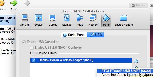
Now, every time you connect your XBee dongle, it will get connected inside your virtual machine. Go ahead and reconnect your XBee dongle.
If you run dmesg on your Ubuntu machine, you should see a similar output:
$ dmesg | tail
[ 6191.654557] usbserial: USB Serial support registered for generic
[ 6191.658496] usbcore: registered new interface driver ftdi_sio
[ 6191.658827] usbserial: USB Serial support registered for FTDI USB Serial Device
[ 6191.659117] ftdi_sio 1-2:1.0: FTDI USB Serial Device converter detected
[ 6191.659178] usb 1-2: Detected FT232RL
[ 6191.659182] usb 1-2: Number of endpoints 2
[ 6191.659185] usb 1-2: Endpoint 1 MaxPacketSize 64
[ 6191.659187] usb 1-2: Endpoint 2 MaxPacketSize 64
[ 6191.659190] usb 1-2: Setting MaxPacketSize 64
[ 6191.667270] usb 1-2: FTDI USB Serial Device converter now attached to ttyUSB0
ttyUSB0 is your device:
$ ls -al /dev/ttyUSB0
$ crw-rw---- 1 root dialout 188, 0 Oct 25 12:42 /dev/ttyUSB0
As you can see, the only group able to write to this device is dialout. We need to add a current user to this group:
$ sudo adduser $USER dialoutMake sure to re-login to get those write permissions.
If your device is named exactly as above, you don’t need to change anything else. But if it is different, you need to modify one Python script, located in arduino_bot_ros package:
$ roscd arduino_bot_ros
$ nano src/scripts/cmd_vel_listener.py
Then, find the line DEVICE = ‘/dev/ttyUSB0’ and change it, so that it points to your device. Press CTRL+X and when it asks you to save, type ‘y’ + ENTER.
Make sure to set the UART switch on the XBEE shield back to the UART position (you only use a DLINE when programming your Arduino).
At this point, your ROS node is ready and your Arduino is configured to receive wireless commands. Time to start the ROS:
$ roscore
<...>
auto-starting new master
process[master]: started with pid [5588]
ROS_MASTER_URI=http://linuxvm:11311/
setting /run_id to e3127026-5c68-11e4-9c28-080027f27617
process[rosout-1]: started with pid [5601]
started core service [/rosout]You should see a similar output, which means roscore started successfully. Now, you need to open another terminal window and start arduino_bot_ros node:
$ rosrun arduino_bot_ros cmd_vel_listener.pyIt should not give you any error messages. Now, the only thing left to do is to set up the ROS teleop_twist_keyboard package:
$ sudo apt-get install ros-indigo-teleop-twist-keyboard
$ rosrun teleop_twist_keyboard teleop_twist_keyboard.py
You should get a similar output:
Reading from the keyboard and Publishing to Twist!
---------------------------
Moving around:
u    i    o
j    k    l
m    ,    .
The keys i,j,k,l,m are your control commands. Press those and your bot should start moving. To better understand what is going on behind the scenes, you could install the rqt package for ROS:
$ sudo apt-get install ros-indigo-rqt ros-indigo-rqt-common-plugins
$ rqt_graph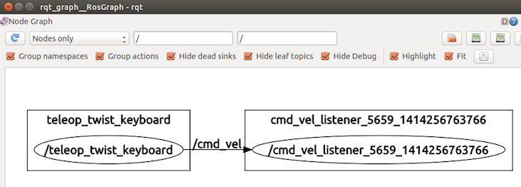
As you can see, there are two nodes - ‘/teleop_twist_keyboard’ and ‘/cmd_vel_listener_XXX_XXXX’. The first one is the one that interacts with your keyboard. The second one sends commands over the ZigBee network. Both communicate over /cmd_vel topic, which means instead of teleop_twist_keyboard, you could use anything else, as long as it can publish to the same topic.
So there it is, a complete Arduino - XBee - ROS example.